Calibrating the measuring tool
The following tasks should be performed only by well-trained and qualified persons. The legalities with regard to performing an accuracy check or calibration of a measuring tool must be known.
- Perform calibration of the measuring tool with extreme precision or have the measuring tool checked by a Bosch customer service agent. Inaccurate calibration leads to incorrect measuring results.
- Only start the calibration if you have to perform a calibration of the measuring tool. As soon as the measuring tool is in calibration mode, you must perform the calibration meticulously to the end in order to ensure that no incorrect measuring results are produced afterwards.
Check the levelling accuracy after every calibration see Accuracy Check of the Measuring Tool. If the deviation is outside the maximum permitted limits, have the measuring tool checked by a Bosch customer service agent.
X-axis and Y-axis Calibration
The GRL 600 CHV can only be calibrated using the LR 60 laser receiver, and the GRL 650 CHVG can only be calibrated using the LR 65 G. The laser receiver must be connected to the measuring tool via Bluetooth® see Establishing a connection to the remote control/laser receiver.
The positions of the measuring tool and laser receiver cannot be changed during calibration (with the exception of the alignments or rotations described). Therefore position the measuring tool on a firm, level surface and secure the laser receiver.
Calibration should be performed via the Bosch Levelling Remote App if possible. There is less likelihood of error when controlling the tool via the app. Otherwise, the measuring tool's position can be altered if buttons are pressed without due care.
For calibration without the app, the corresponding buttons on the measuring tool must be pressed. It is not possible to use the remote control during calibration.
A free measuring distance of 30 m on a firm surface is required. If no such measuring distance is possible, calibration can also be performed with lower levelling accuracy on a measuring distance of 15 m.
Mounting the measuring tool and the laser receiver for calibration:
Mount the measuring tool in the horizontal position 30 m or 15 m from the laser receiver on the tripod (43) or position it on a firm, level surface.
Secure the laser receiver at the correct height:
- Either to a wall or to another surface by means of magnets or the suspension hook on the laser receiver,
- or to a securely fastened aid with the holder for the laser receiver.
To do this, consult the operating instructions for the laser receiver.
Aligning the measuring tool for calibration:
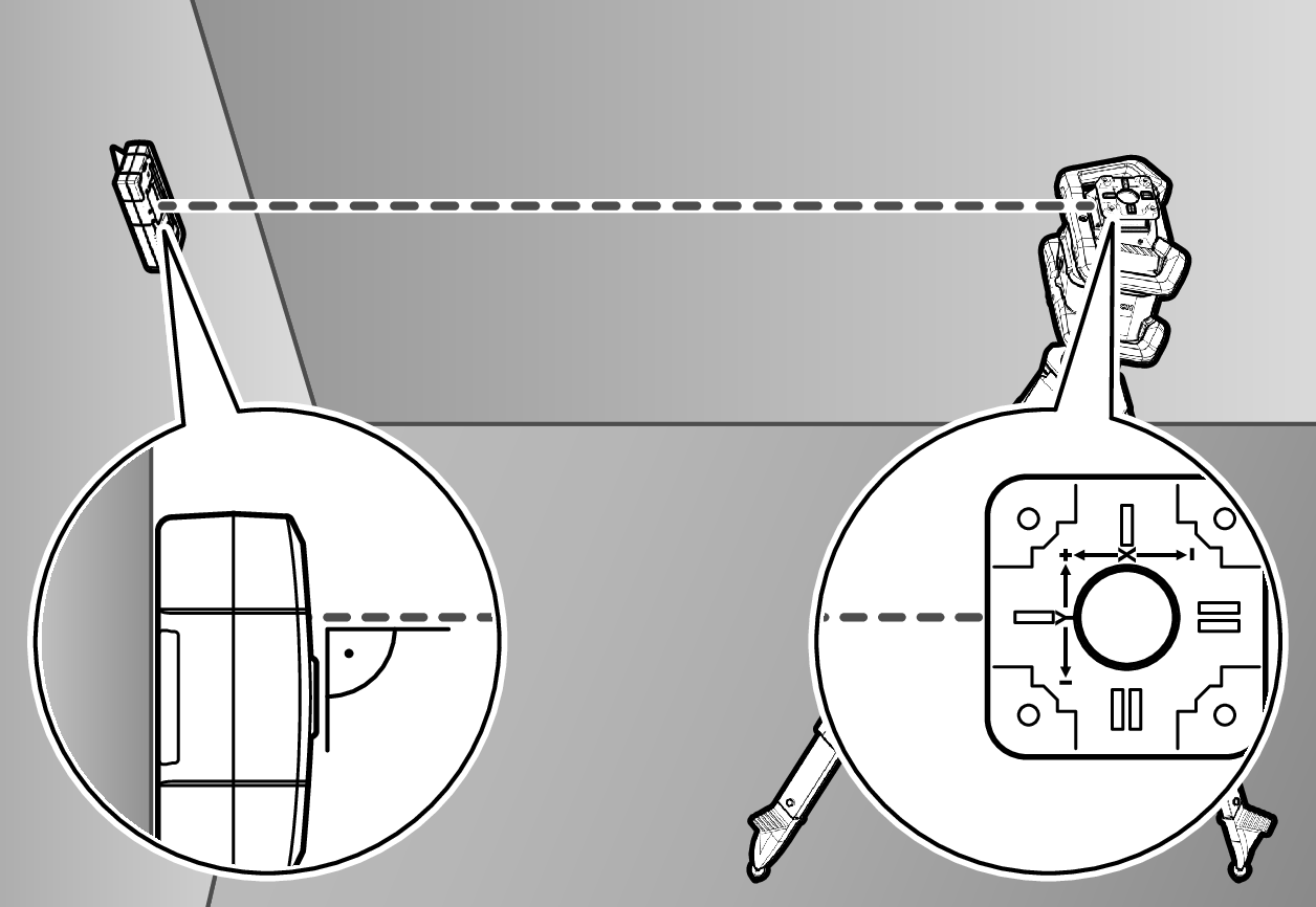
Align the measuring tool so that the X-axis indicator imprinted on the measuring tool with the "+" side is pointing to the laser receiver. For this, the X‑axis must be perpendicular to the laser receiver.
To start calibration:
- For calibration via the Bosch Levelling Remote App: Switch on the measuring tool. Start calibration in the app. Follow the instructions in the app.
- For calibration without the app: Switch on the measuring tool and the laser receiver. Make sure that both of these are connected via Bluetooth®. Start calibration by pressing the on/off button on the laser receiver and the CenterFind mode button on the laser receiver at the same time. "CAL" will appear on the display of the laser receiver.
Press and hold the CenterFind mode button on the laser receiver to cancel the calibration, if required.
To perform calibration without the app:
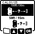
In the menu that appears in the measuring tool display after starting calibration, select the existing distance between the measuring tool and the laser receiver. To do this, press the ▲ button (4) or the ▼ button (3). Confirm your selection with  by pressing the slope button (14).

To confirm the selected measuring distance including the corresponding levelling accuracy (), press the slope button (14) in the menu which subsequently appears. To go back to selecting the measuring distance ( ), press the line operation button (5).
Align the height of the laser receiver so that the variable laser beam (8) on the laser receiver is indicated as "centred" (see operating instructions for the laser receiver). Secure the laser receiver at this height.
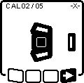
Check whether the measuring tool and laser receiver are aligned with each other, as illustrated on the display (the "+" side of the X-axis is aligned to the laser receiver). Start calibration of the X-axis with  by pressing the slope button (14).
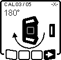
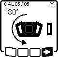
If this step appears on the display, rotate the measuring tool 180° so that the "–" side of the X‑axis is directed at the laser receiver. For each rotation, take care not to change the height and inclination of the measuring tool. Confirm the rotation with by pressing the slope button (14). Calibration of the X-axis continues.

This symbol will appear on the measuring tool display if the X-axis has been successfully calibrated.
Continue calibration with by pressing the slope button (14).

To calibrate the Y-axis, rotate the measuring tool 90° in the direction of the arrow so that the "+" side of the Y‑axis is directed at the laser receiver. Confirm the rotation with by pressing the slope button (14).
If this step appears on the display, rotate the measuring tool 180° so that the "–" side of the Y‑axis is directed at the laser receiver. Confirm the rotation with by pressing the slope button (14). Calibration of the Y-axis continues.
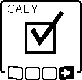
This symbol will appear on the measuring tool display if the Y-axis has been successfully calibrated.
Finish the calibration of the Y-axis with by pressing the slope button (14).

This symbol confirms that the X-axis and the Y-axis have been successfully calibrated with the levelling accuracy selected at the beginning. End the calibration with by pressing the slope button (14).
If the calibration has been completed successfully, the measuring tool then automatically switches itself off.
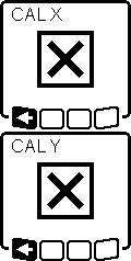
The relevant error message will appear in the measuring tool display if calibration of the X‑axis or the Y‑axis has not been successful. "ERR" will appear on the display of the laser receiver.
Cancel the calibration with by pressing the button for line operation (5).
Make sure that the measuring tool and the laser receiver are aligned correctly (see description above). Restart the calibration.
If calibration fails again, have the measuring tool checked by a Bosch customer service agent.
Z-axis calibration
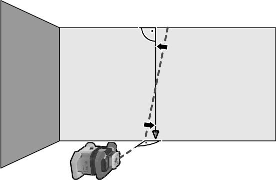
A free measuring distance on firm ground in front of a 10 m wall is required for the calibration. Fix a plumb line to the wall.

Position the measuring tool on a firm, level surface. Switch the measuring tool on and allow it to level in. Align the measuring tool so that the laser beam is perpendicular to the wall and cuts through the plumb line. Switch the measuring tool off.
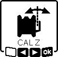
To start calibration mode, press and hold the slope button (14) and then also briefly press the on/off button (11). The measuring tool is switched on. Allow the measuring tool to level in.
Align the laser beam so that it runs as parallel as possible to the plumb line.
Tilt the laser beam in the ◀ direction by pressing the ▲ button (4). Tilt the laser beam in the ▶ direction by pressing the ▼ button (3).
If it is not possible to align the laser beam in parallel to the plumb line, align the measuring tool to the wall more precisely and start the calibration process again.
If the laser beam is aligned in parallel, save the calibration with by pressing the slope button (14).

This symbol confirms that the Z-axis has been calibrated successfully. At the same time, the status indicator (12) will flash green three times. End the calibration with by pressing the slope button (14).
If the calibration has been completed successfully, the measuring tool then automatically switches itself off.
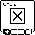
This error message will appear if calibration of the Z-axis has been unsuccessful. Cancel the calibration with by pressing the button for line operation (5).
Ensure that the reference vertical line is in the pivoting range of the rotation head and restart the calibration. Make sure that the measuring tool is not moved during calibration.
If calibration fails again, have the measuring tool checked by a Bosch customer service agent.