Accuracy Check of the Measuring Tool
The largest influence is exerted by the ambient temperature. In particular, temperature differences that occur from the ground upwards can refract the laser beam.
In order to minimise thermal influences resulting from heat rising from the floor, it is recommended that you use the measuring tool on a tripod. In addition, position the measuring tool in the centre of the work surface, wherever this is possible.
In addition to external influences, device-specific influences (e.g. falls or heavy impacts) can also lead to deviations. For this reason, check the levelling accuracy each time before beginning work.
First check the height accuracy and levelling accuracy of the horizontal laser line, then the levelling accuracy of the vertical laser line.
Should the measuring tool exceed the maximum deviation during one of the tests, please have it repaired by a Bosch after-sales service.
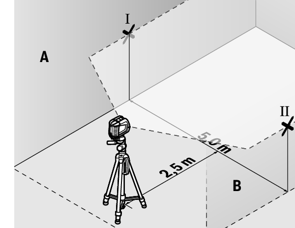
For this check, you will need a free measuring distance of 5 m on firm ground between two walls (designated A and B).
- Mount the measuring tool close to wall A on a tripod, or place it on a firm, level surface. Switch on the measuring tool. Select cross-line mode with automatic levelling.
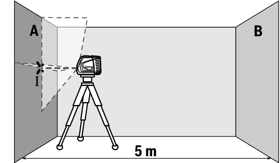
- Aim the laser at the closer wall A and allow the measuring tool to level in. Mark the middle of the point at which the laser lines cross on the wall (point I).
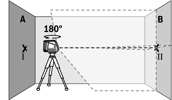
- Turn the measuring tool 180°, allow it to level in and mark the point where the laser lines cross on the opposite wall B (point Ⅱ).
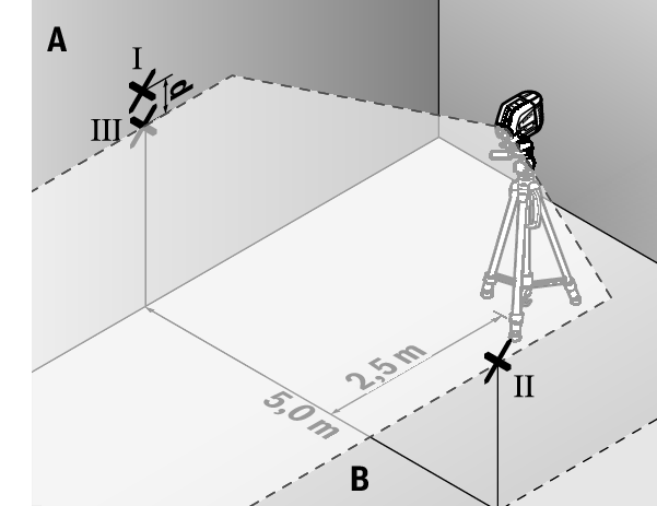
- Position the measuring tool – without rotating it – close to wall B, switch it on and allow it to level in.
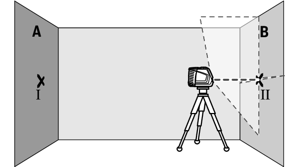
- Align the height of the measuring tool (using the tripod or by placing objects underneath as required) so that the point where the laser lines cross exactly hits the previously marked point Ⅱ on wall B.
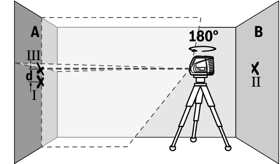
- Turn the measuring tool 180° without adjusting the height. Aim it at wall A such that the vertical laser line runs through the already marked point Ⅰ. Allow the measuring tool to level in and mark the point where the laser lines cross on wall A (point Ⅲ).
- The discrepancy d between the two marked points Ⅰ and Ⅲ on wall A reveals the actual height deviation of the measuring tool.
The maximum permitted deviation on the measuring distance of 2 × 5 m = 10 m is as follows:
10 m × ±0.3 mm/m = ±3 mm. The discrepancy d between points Ⅰ and Ⅲ must therefore amount to no more than 3 mm.
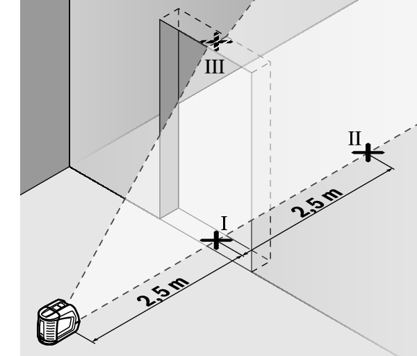
For this check, you will need a free area of 5 × 5 m.
- Mount the measuring tool in the middle between walls A and B on a tripod, or place it on a firm, level surface. Select horizontal mode with automatic levelling and allow the measuring tool to level in.
- At a distance of 2.5 m from the measuring tool, mark the centre of the laser line on both walls (point Ⅰ on wall A and point Ⅱ on wall B).
- Set up the measuring tool at a 5 m distance and rotated by 180° and allow it to level in.
- Align the height of the measuring tool (using the tripod or by placing objects underneath as required) so that the centre of the laser line exactly hits the previously marked point Ⅱ on wall B.
- Mark the centre of the laser line on wall A as point Ⅲ (vertically above or below point Ⅰ).
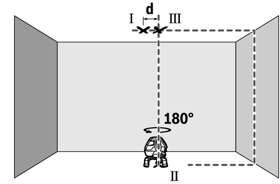
- The discrepancy d between the two marked points Ⅰ and Ⅲ on wall A reveals the actual horizontal deviation of the measuring tool.
The maximum permitted deviation on the measuring distance of 2 × 5 m = 10 m is as follows:
10 m × ±0.3 mm/m = ±3 mm. The discrepancy d between points Ⅰ and Ⅲ must therefore amount to no more than 3 mm.
For this check, you will need a door opening (on solid ground) which has at least 2.5 m of space either side of the door.
- Place the measuring tool 2.5 m away from the door opening on a firm, flat surface (not on a tripod). Select cross-line mode with automatic levelling. Aim the vertical laser line at the door opening and allow the measuring tool to level in.
- Mark the centre of the vertical laser line on the floor of the door opening (point Ⅰ), 5 m away on the other side of the door opening (point Ⅱ) and on the upper edge of the door opening (point Ⅲ).

- Rotate the measuring tool 180° and position it on the other side of the door opening, directly behind point Ⅱ. Allow the measuring tool to level in and align the vertical laser line in such a way that its centre passes through points Ⅰ and Ⅱ exactly.
- Mark the centre of the laser line on the upper edge of the door opening as point Ⅳ.
- The discrepancy d between the two marked points Ⅲ and Ⅳ reveals the actual vertical deviation of the measuring tool.
- Measure the height of the door opening.
You can calculate the maximum permitted deviation as follows:
Doubled height of the door opening × 0.3 mm/m
Example: At a door opening height of 2 m, the maximum deviation amounts to
2 × 2 m × ±0.3 mm/m = ±1.2 mm. The points Ⅲ and Ⅳ must therefore be no further than 1.2 mm from each other.
For this check, you will need a clear measuring space on firm ground with a distance of approx. 5 m between the floor and the ceiling.
- Mount the measuring tool onto the rotating platform (16) and place it on the floor. Select vertical mode with automatic levelling and allow the measuring tool to level in.

- Mark the centre of the top point of intersection of the laser lines on the ceiling (point Ⅰ). Also mark the centre of the plumb point on the floor (point Ⅱ).
- Turn the measuring tool by 180°. Position it so that the centre of the plumb point falls onto the marked point Ⅱ. Allow the measuring tool to level in. Mark the centre of the top point of intersection of the laser lines (point Ⅲ).
- The discrepancy d between the two marked points Ⅰ and Ⅲ on the ceiling reveals the actual deviation of the measuring tool from the vertical plane.
You can calculate the maximum permitted deviation as follows:
Doubled distance between floor and ceiling × 0.6 mm/m
Example: At a floor-to-ceiling distance of 5 m, the maximum deviation amounts to
2 × 5 m × ±0.6 mm/m = ±6 mm. The points Ⅰ and Ⅲ must therefore be no further than 6 mm from each other.