Accuracy Check of the Measuring Tool
Check the levelling and display accuracy of the measuring tool each time before beginning work and after longer transport of the measuring tool.
Move the air bubble of the circular bubble vial (7) to a position midway between the end position of the check and the centre by turning the levelling screws (12).
Using the hex key (17), turn the adjusting screws (11) until the air bubble is positioned in the centre of the circular bubble vial.
Check the circular bubble vial by rotating the telescope by 180°. Repeat the adjustment procedure if necessary or contact Bosch customer service.
After aligning and focusing the measuring tool, measure the height at a reference point. Then press and release the locking button of the compensator (8). Measure the height at the reference point again.
If the two heights do not match exactly, have the measuring tool repaired by Bosch customer service.
A measuring distance of approx. 30 m is required for the check. Set up the measuring tool in the centre and levelling rods A and B at both ends of the measuring distance.
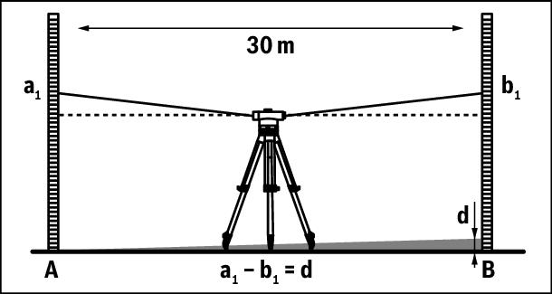
After aligning and focusing the measuring tool, read off the heights at both levelling rods. Calculate the difference d between the height a1 on levelling rod A and the height b1 on levelling rod B.
Example:
a1 = 1.937 m
b1 = 1.689 m
a1 – b1 = 1.937 m – 1.689 m = 0.248 m = d
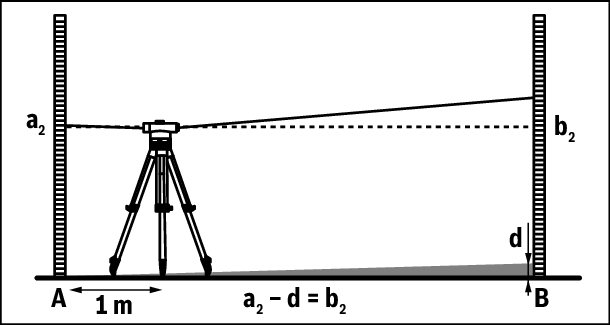
Set up the measuring tool approx. 1 m away from levelling rod A. After aligning and focusing the measuring tool, read off the height a2 at levelling rod A.
Subtract the previously calculated value d from the measured height a2 in order to obtain the set value for the height b2 at levelling rod B.
Measure the height b2 at levelling rod B. If the measured value deviates by more than 6 mm (GOL 20 D/G), 3 mm (GOL 26 D/G) or 2 mm (GOL 32 D/G) from the calculated set value, the crosshairs must be readjusted.
Example:
a2 = 1.724 m
d = 0.248 m
a2 – d = 1.724 m – 0.248 m = 1.476 m
GOL 20 D/G: When measuring, the height b2 must be 1.476 m ± 6 mm.
GOL 26 D/G: When measuring, the height b2 must be 1.476 m ± 3 mm.
GOL 32 D/G: When measuring, the height b2 must be 1.476 m ± 2 mm.
Unscrew the eyepiece cover (4). Using the adjusting pin (18), turn the adjusting screw (5) clockwise or anticlockwise, until the calculated set value for the height b2 is reached when measuring on levelling rod B.
Screw the eyepiece cover (4) back on.
Example:
When measuring b2, the value 1.476 m must be set.
Check the crosshairs again. Repeat the adjustment procedure if necessary or contact Bosch customer service.